This article will give technical details on the hardware capabilities used to implement our KASAN.
I’d like to point out that the KASAN implementation is not specific to this chip. The only features needed for the KASAN to theoretically work are :
- an exception handling mechanism.
- an
MPU.
The chip#
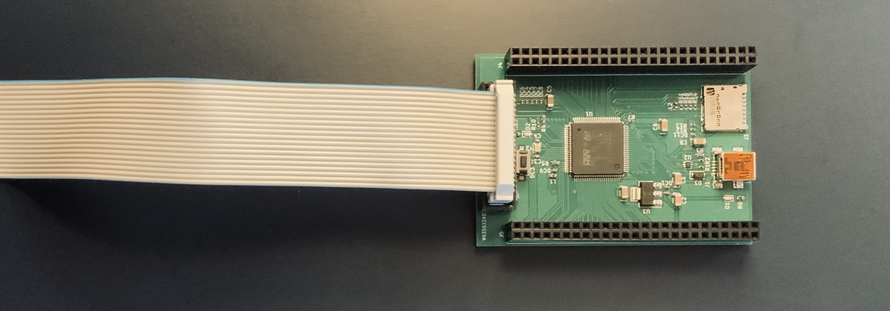
Let’s introduce the development board on which I built the KASAN.
The devboard that my dear wife made for me has :
- STM32H750 processor; featuring
- a CortexM7 CPU implementing the
ARMV7Marchitecture; - a Memory Protection Unit (
MPU) conforming to theARMV7Marchitecture; - a Floating Point Unit;
- 128KiB of Flash;
- TODO Around 512KiB of RAM.
The MPU is the main component on which our KASAN implementation will be based. It is a needed feature.
Execution privileges#
A processor implementing the ARMV7M architecture has two levels of privileges :
- unprivileged mode : code running in this privilege level has limited access to the processor system registers.
- privileged mode : code running in this privilege level has unlimited access to all processor features.
In particular, the CPU starts in privileged mode at reset. Then, it is up to the firmware (kernel) to run threads in unprivileged mode.
Code running in unprivileged mode can do a system call to execute a system handler. This handler will execute in privileged mode. The actual function that will be executed can’t be programmed by unprivileged software.
Stacks#
A processor implementing the ARMV7M architecture supports two different stacks :
- the Main Stack, used in
handler mode. Stack pointer :MSP - the Process Stack (should have been called Thread Stack), used in
thread mode. Stack pointer :PSP.
The MSP / PSP are aliased to SP. Accessing SP actually accesses the stack pointer active in the current mode (thread or stack).
Exceptions#
A processor implementing the ARMV7M architecture supports the notion of exception : code running at a given time can be temporarily stopped, for another piece of code (a handler) to be executed instead.
When the handler is done (understand : when the handler function returns), the stopped code resumes its execution transparently. This mechanism is purely hardware, and serves among other things, to handle system calls and interrupts.
The piece of code that is executed is called a handler; when the processor handles an exception, it is said to be in handler mode.
When it doesn’t, it is said to be thread mode.
Thread mode can be privileged or not.
Handler mode is always privileged.
An exception has an ID, which is used to determine :
- if this exception is enabled (i.e. if the handler is allowed to be called at all when the exception is triggered).
- the priority of this exception (i.e if the handler is allowed to be called given the currently executed exception, if any).
- the handler to be executed : handlers addresses are listed in a table in memory called the
vector table. The location of the vector table is defaulted at boot and can be changed later by configuring theVTOR(Vector Table Offset Register) register.
The ARMV7M architecture supports at most 512 exceptions.
The ARMV7M architecture defines the 16 first exception IDs as system exception
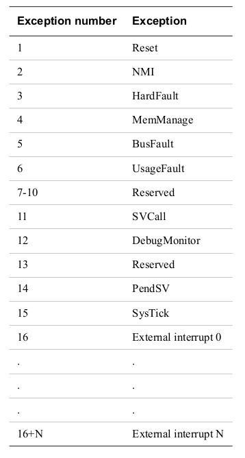
Those system exceptions are interesting for us :
- Reset : function called when the processor is reset.
- NMI : function called when the
Non Maskable Interruptexception is triggered. - HardFault : handler for certain non-recoverable faults, or for some faults occurring inside their related handler (ex : nested memfault).
- MemFault : handler for a MPU access fault (see after) and others.
- BusFault : handler for invalid transactions on the memory bus.
- UsageFault : handler for misuse of the assembly (ex : division by zero).
- SVCall : syscall handler.
- DebugMonitor : handler for debug events when there is no debugger.
- PendSV : preemption handler.
- Systick : system timer overflow handler.
The reader may have noticed that no exception has index 0. This is on purpose, as the first 32 bit word of the exception table used during reset contains the stack pointer loaded during reset.
The (at most) 496 remaining exceptions are interrupts.
When an exception A is triggered, the processor determines the priority of A, so as the priority of B, the exception currently handled by the processor, if any. If A is enabled and has a greater priority than B (or if the processor is not currently executing any exception), the current execution context is saved in the local stack (either Main Stack or Process Stack) by the hardware, and the handler of A executed. When the handler of A is complete (when it returns), the processor detects it, and restores the execution context saved on exception entry. Then, the execution of B (or thread code) continues transparently.
Context#
The ARMV7M context is composed of
- general purpose registers :
R0->R3: Caller-saved.R4->R11: Callee-saved.R12: Caller saved, scratch register.R13: Caller saved, Stack pointer, alias :SP.R14: Caller saved, Link register, alias LR.R15: Caller saved, Program counter, alias PC.
- Floating point registers (When FPU is implemented and active) :
S0->S15: Caller saved.S16->S31: Callee saved.
- Status registers :
xPSR: composite of all status registers, see theARMV7MARM for more details.
Context saving and exception#
Saving the execution context means atomically storing a subset of the context registers to the currently used stack (Main / Process). Restoring the execution context means atomically loading a subset of the context registers from the stack, and as such, updating the state of the processor. (The loaded subsets and the stored subsets are the same).
In the ARMV7M architecture, This subset of saved/restored registers is composed of all the caller-saved registers and of the program status registers.
This makes the exception entry / return procedures follow the standard ARMV7M calling conventions, and allows us to implement exception handlers using C code only when required (not here lol).
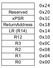
Here is the set of context saved registers when the FPU is not enabled :
Here is the set of context saved registers when the FPU enabled :
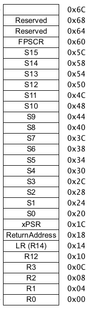
Reserved words may be omitted to achieve that purpose.
Please refer to the ARMV7M Architecture Reference Manual for an exact description.If after a context save, the stored value of a register is modified, the modified value will be loaded in the register during context restore. This will be the base trick on top of which we will build our emulator.
MPU#
The ARMV7M features an optional MPU, always implemented in the CortexM7.
The MPU for Memory Protection Unit, allows the kernel to define up to 8 or 16 (depending on the implementation) MPU regions, and to define
access permissions for these MPU regions.
These MPU regions must be :
- of a size that is a power of 2 and that is greater or equal than 32 bytes.
- aligned on their size (start address is a multiple of the size).
If an access is made in one of those regions, with incorrect permissions (ex : write to a location in non-writable region, executing a location in a non-executable region), the MPU will issue a permission fault, and the MemManage exception will be triggered, causing the interruption of the program that caused the access, the saving of the register context, and the execution of the MemManage handler.
I will not elaborate a lot on the various access permissions since that would require a chapter of its own, with little added value. What is important to us is that the MPU allows us to :
- blacklist a memory block, i.e. prevent the CPU from accessing this memory block while the
MPUis active. - whitelist a memory block, i.e. allow the CPU from accessing this memory block while the
MPUis active.
The MPU regions are indexed from 0 to N (N = nb_mpu_regions - 1), and have a fixed priority : when determining the access permissions for a byte at address X, if multiple MPU regions (let’s say A and B) cover X, then the MPU region with the highest index max(A, B) will be selected to decide which permissions use to access X.
That allows us, for example, to blacklist a large memory block using a MPU region with low priority, and to whitelist smaller portions of this memory block using MPU regions with a higher priority : when an access to one of the smaller blocks will be made, both the whitelist and the blacklist MPU regions will be considered, but since the whitelist MPU region has a higher priority, it will be selected and access will be allowed.
This will be the base trick on top of which we will build the memory access checking system.